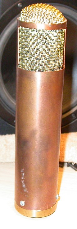
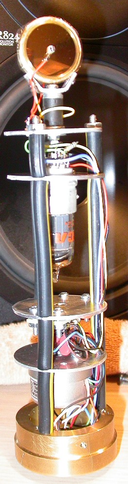
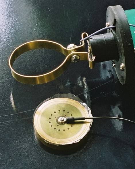
These are photos of my DIY tube microphone. Details? The capsule is my attempt at duplicating a Neumann M7 capsule. The capsule uses a glued-in diaphragm (like the M7) but made of 6 micron mylar (unlike the M7's 10 micron PVC material). A gold coating of somewhere between 50 and 150 angstroms has been applied to the film (I do that too). It is tensioned to a resonance of about 950 Hz, which is quite similar to the tuning of the original M7 capsules. The rubber stuff you see lining the studs in the microphone is epichlorohydrine automotive vacuum hose. It was used to damp out any resonances in the structure, and to prevent rattling of the internal bits against the microphone shell. The tube is a 6AH6, which has a very high gain and a very low output impedance. It also has a fairly high capacitance between electrodes when wired in triode mode, and this capacitance and gain is a very important part of the performance of a microphone amplifier circuit. It can be used in place of the more traditional 6AU6, but the output is higher and more solid. The output transformer is a high-quality Sowter part, and additional components are soldered to a turret board located between the tube and transformer. Power supplied to this microphone include a 120 volt DC power feed and a 450 mA constant current source (typically 7.3 volts) used to drive the filament of the tube and also to provide a one volt bias to the cathode. This allows the amplifier to dispense with the traditional cathode bypass capacitor - other than power supply filtering, no electrolytic capacitors are used in the signal path.
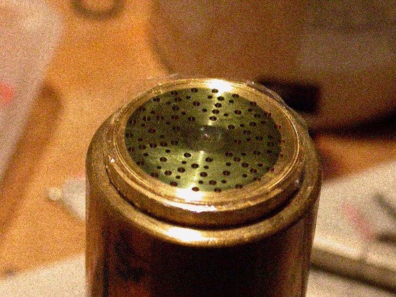
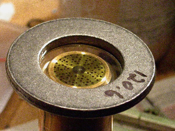
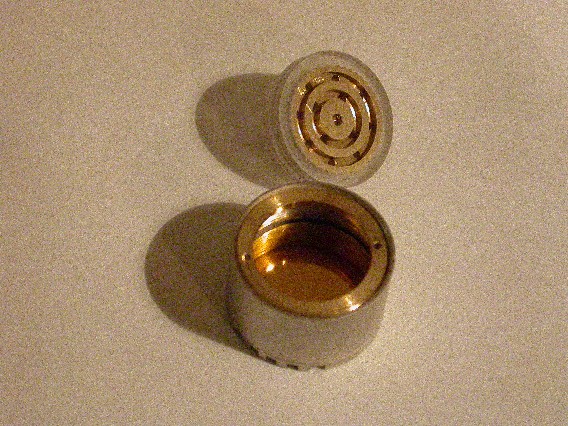
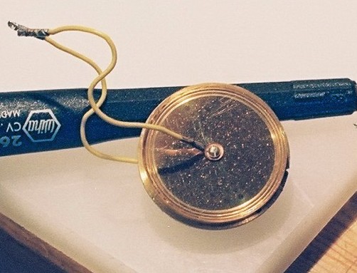
This is a photo of a semi-completed M7-like capsule. This has had its terminal removed as the hole depth was incorrect on this version. My working version (above) uses a blind hole depth of 4mm, this one was 2.5mm, otherwise these two capsules are identical. The sound was devoid of any high-end with the 2.5mm depth. This is obviously fixed with the correct depth. Diaphragm material is 6 micron metallized mylar, tensioned to 950 Hz. Diaphragm tuning is not as critical on the Neumann capsule design as it is on the Siemens/AKG capsule shown later on this page...
This is a photo of tensioning the diaphragm. This is just a photo shoot - the diaphragm in question was wrecked by careless application of glue. A glued diaphragm is attached by gluing the underside of the diaphragm to the capsule and it's easy for the glue to wick underneath the diaphragm and ruin the works. This diaphragm met that fate, but was recycled to show you how I tension the diaphragms. A mass of 120 grams should result in a diaphragm resonant frequency of about 950 Hz. Care must be taken while mounting the diaphragm to the mounting ring to ensure even tension distribution. I have found that usually the diaphragm ends up working well if this is done. The Neumann style capsule is tuned this way at the factory.
These are diaphragms with the gold coating deposited. The ones on the left are for edge-terminated capsules, the ones on the right are for centre-terminated capsules. Note the ones for edge-terminated capsules are fully coated, the ones for centre-terminated capsules only are partially coated. The photo above shows the coated and uncoated portions of the diaphragm. The light green colour is the gold coating - it is typically applied so thin that it turns green under bright light.
This is my latest capsule creation, a multi-chambered capsule built using the AKG original CK12 patent for measurements. No audio files yet, but so far it sounds pretty good. I built three pairs of plates, the ones shown are 170 micron gap, the ones in the mic are 220 microns, and another pair use the patent dimension of 150 microns. A 40 micron spacer is used between the capsule halves. This spacer is used to tune the frequency response, and I have not taken the time to adjust this carefully yet. I suspect that careful adjustment will make the capsule come alive.
These are closer photos of some backplates - these are the ones that didn't sound good. Clockwise from the upper left, Neumann M7-like capsule, incorrect blind hole depth, no high frequency response. My capsule design, an ok sound, but nothing special - similar hole numbers and sizes to an M7 but straight lines instead of a circuilar pattern. My capsule design, cross between a K67/87 and M7 - poor polar pattern and a spitty high end. Another attempt at the K67/87 and M7 cross - awful sound altogether. The winner? the M7 that is in the microphone shown at the top. The next place winner is the CK12 copy shown in the photo above.
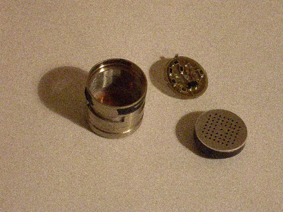
This is a photo of a cathode-follower 5840 small-diaphragm condensor. The capsules used are the AKG CK-6x-ULS family from the C460 and C480 family. The submini tube is shown attached to the Tuchel connector. A damping ring used on the tube is not shown here.
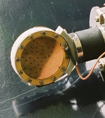
This is the capsule off of an Apex 180. I am not sure the backplate is the source of the sound I don't care for on this mic. My feeling is the capsule housing has a resonance at about 8 kHz somewhere - possibly due to the very large distance from the sound opening to the diaphragm.
This is an AKG C1000 capsule and FET amplifier. I don't know what makes this mic as sucky as it is, but it is what it is. The electret material is coated on the backplate as a very thin layer. The capsule guts look a lot like the C451B capsule, which is not sucky at all.
This is a Debenham, Stebbings, and Robinson capsule. It sounds very nice and is not very fussy as to diaphragm tensioning. Recommended for a first DIY. Outer plastic is Delrin. To stick it to brass, you MUST use Loctite 770 primer followed by the thinnest cyanoacrylate you can find.
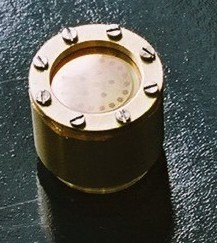
This is an easy to DIY mic capsule holder. It's made of 3/16" brass strip, cut, shaped, and soldered at one joint at the bottom. You need three holes drilled, but it's easy to mount and does not require strange machining on the capsule to mount it.
This is the same capsule holder with the capsule taken out.
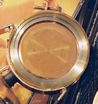
And this is what 45 years does to a PVC capsule. This original M7 capsule (from a U47) has dried out, and the gold layer has cracked in several places. This makes the capsule have almost no output unless it gets damp. Then it works, until the dampness shorts it out.
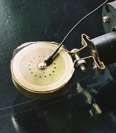
Finally, this is a shot of a Sony C38 capsule, with its original polyester film diaphragm. This is a nice sounding mic capsule, simple to assemble, but the tube or amplifier needs special attention to be quiet, as its output is about 15dB lower than its M7 cousin as shown above.
I couldn't resist making a small diaphragm condensor. This is an omni, meant to connect to the C460/C480 AKG amplifier bodies.
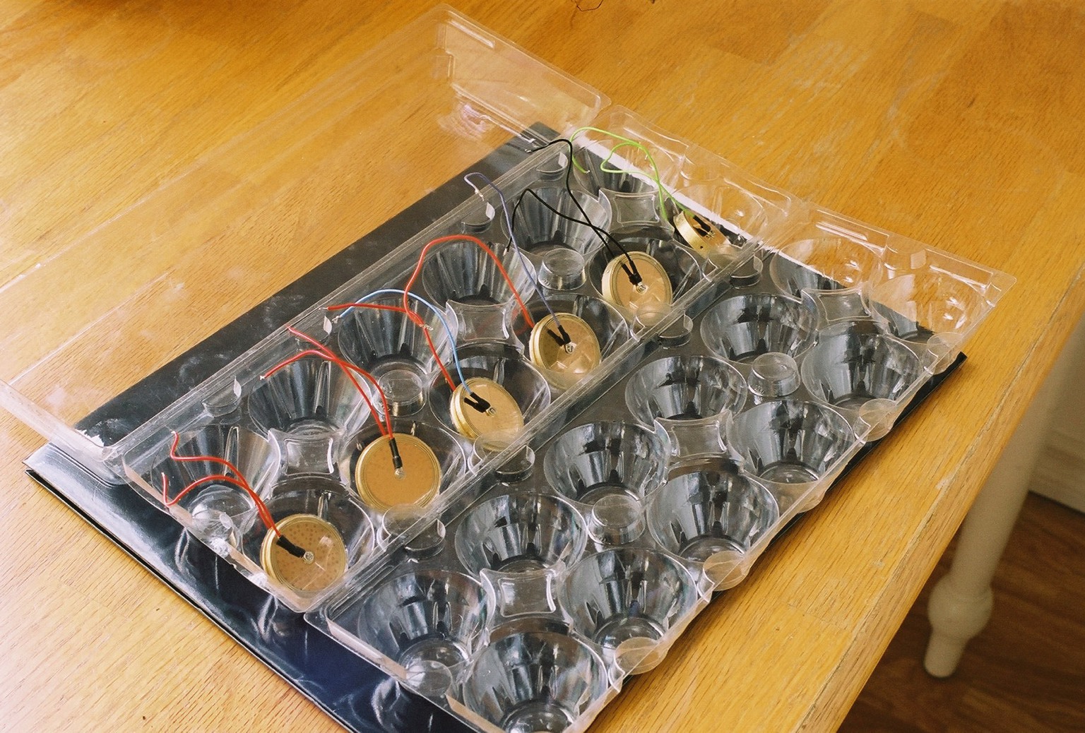
And here are six capsules, tested, and ready to go.
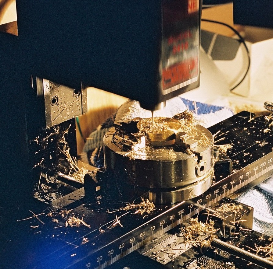
And this is CNC drilling of the capsule. A 4-jaw chuck is used to hold the capsule blank in place, while the mill drills all of the holes precisely where they are supposed to be. I use carbide printed circuit board drill bits as fast as the mill will run.